RadioMaster have just released a bunch of ELRS receivers specially for gliders and electric models. These are notable for being some of the first ELRS receivers to incorporate servo connectors - no need for a separate PWM converter board.
I've been evaluating these receivers including flight testing them in DLG and F3F models. Let's take a closer look...
Four ELRS receivers for gliders
The receivers submitted for review are the ER6G and ER6GV (6-channel), and the ERG8 and ER8GV (8-channel). They all have the following features in common:
- PWM outputs
- Dual whisker antennae
- WiFi enabled (ESP32)
- Built-in telemetry including RxBt, RSSI, RQly
- Vario sensor ('V' receivers only)
- Remote binding
- Operating voltage of 3.5 - 8.4V
- Telemetry of external voltage
All units were supplied with ELRS 3.2.1 installed. Let's now look at each receiver in more detail:
ER6G receiver
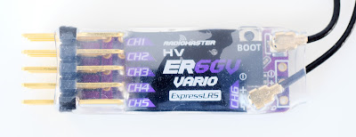
The ER6G is a compact single-board 6-channel receiver. Weight is just 5 grams.
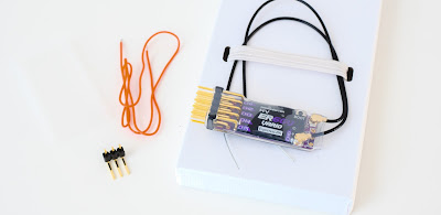
Included in the package is a connector for CH6, and a wire for external voltage telemetry.

|
| Rx with CH6 connector, and wire for external voltage telemetry |

|
| 'V' version has integrated vario |
Protection
The receiver is wrapped in heatshrink tube. Two spare lengths of heatshrink are provided in case you make the channel 6 mod (see below).
The antenna connectors lack the usual yellow glue, instead they rely on the heatshrink to keep them in place.
Adding the channel 6 connector
As supplied there are only five PWM pins available. If you need six channels then you could solder in the supplied PWM pins. However, I didn’t like this approach because (a) the pins would interfere with one of the antennae, and (b) the pins would have to be end facing in order to clear the components, which would greatly increase the length of the unit. Instead, I've put CH6 on a flying lead.
To avoid pressure on the reset button, I bored a hole through the heatshrink using the sharpened end of a brass tube.

|
| Channel 6 flying lead mod (heatshrink covering not yet applied) |
Battery connection (don't use the CH6 port!)
According to the instructions, power must be supplied through one of CH 1-5 pins, not CH6. This is because CH 1-5 share a robust power bus, whereas the CH6 power lines are tapped via tracks on the PCB.
This means that if you’re using six servos, or five servos and no CH6 connector, then a Y-lead will be needed to share a port between a servo and the battery, and this does increase the bulk of the unit.
Voltage telemetry
It's a good idea to calibrate the RxBt telemetry (my ER6G was under reading by 0.2 V). Use a meter to measure the voltage and adjust the sensor offset in the Telemetry menu.
The voltage range for external telemetry is 3.0 - 26 V.
S.Bus support
The forthcoming ELRS V3.3 will enable one of the PWM ports to be repurposed for S.Bus. One possibility would be PWM for the fuselage servos, and S.Bus for the wing servos (an S.Bus to PWM converter will of course be needed if the servos don't support S.Bus).
Compared with the FrSky RX6R
The ER6G might seem an obvious candidate to replace the popular FrSky RX6R. However, while the ER6G is slimmer, it is also longer by ~12 mm. Worth bearing in mind for tighter installations.

|
| FrSky RX6R and RM ER6G compared |
Flight testing the ER6GV in a DLG
For flight testing the ER6GV I used my TopSky 1.5 m DLG. This is equipped with four servos and 4 x 300 mAh NiMH cells.
The ELRS devs recommend Full Res 8Ch switch mode, with a 100Hz packet rate, and this is what I am using.
I've had several sessions and there have been no problems with control or range. See below, though, for TLM tweaks.
Capturing DLG launch heights.
My DLG templates (4-servo, and 6-servo) offer a launch height callout. In order to capture height with sufficient precision, the telemetry data must be transmitted at a reasonably high rate.
The data rate is determined by the telemetry ratio (TLM). This is the proportion of telemetry frames to all frames in a given time interval. The smaller the ratio, the higher the telemetry rate. TLM is configured in the transmitter, via the ELRS Lua script.
Using a packet rate of 250 Hz, I found that the default TLM (1:64) did not provide sufficient resolution to capture my launch heights accurately. Decreasing TLM to 1:8 made a significant improvement.
Below are extracts from the SD card logs which demonstrate the issue. The log recording interval was 0.4 seconds.
- The left hand plot is with TLM = 1:64 (the default). Note the blocky appearance. From the log, it appears that the ALT telemetry data was refreshed every ~2.8 secs. This is insufficient to capture the launch peaks.
- In the right hand plot, TLM = 1:8. From the plot it can be deduced that the ALT telemetry is being sent every 0.4 seconds or less. I think this is just about sufficient.
ER8G receiver
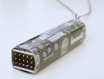
The second receiver provided was the ER8G. This unit has 8 channels. It uses two boards, with connectors at both ends. Length is 60 mm and weight is 12 grams.
The unit is supplied with a UART cable, a length of wire for connecting to the external voltage pad, and two lengths of extra heatshrink tube.

|
| ER8GV receiver. There are PWM outputs at both ends. |
Battery connection
Unlike its junior sibling, the ER8G has a dedicated port for the battery. The unit also supports external voltage telemetry in the range 4.0 - 35 V.
UART
External sensors can be connected via a UART port on the side of the unit. Voltage, current and GPS sensors are planned.
Form factor issues
My only gripe with the ER8G/V is the form factor. At 60mm it's far too long for a modern F3F ship. Also, having servo connectors at both ends complicates installation. (Yes, the ER8G fits in my Sting, however this is an old model with lots of room.)

|
| ER8GV in my Sting F3F model. The length is not ideal! |
Flight testing the ER8G
For flight testing the ER8G I used my Sting F3F moulded glider, with six
servos and 4 x 2100 mAh Eneloops.
I set the Switch Mode to '8-channel'. This provides eight 10-bit
channels in addition to the (reserved) CH5. Max Power is 100 mW with
Dynamic Power enabled.
ELRS reserves channel 5 as an arming channel. For this reason, I moved CH5 (normally for right V-tail) to CH7. I then set CH5 high to indicate 'permanently armed'. For more info on ELRS and CH5, see my Introduction to ELRS (link at end).
The ER8G performed well in spite of using just a single antenna - it turned out that antenna diversity was not enabled! Antenna diversity
is configured via the ELRSv3 Lua script.
Maximum distance reached during the flight was approximately 150 meters.
The maximum recorded RF output was 25mW, and RQly remained at 100% for
almost all the flight, only momentarily dropping to 95%. On would expect improved figures when using both antennas.

Telemetry logs showing link quality (RQly) and transmission
power (TPW2). Three flights.shown.
Incidentally, the little Zorro was fully loaded with F3F template, plus Lua scripts for adaptive trim and adjustable snapflap.
For flight testing the ER8G I used my Sting F3F moulded glider, with six servos and 4 x 2100 mAh Eneloops.
I set the Switch Mode to '8-channel'. This provides eight 10-bit channels in addition to the (reserved) CH5. Max Power is 100 mW with Dynamic Power enabled.
ELRS reserves channel 5 as an arming channel. For this reason, I moved CH5 (normally for right V-tail) to CH7. I then set CH5 high to indicate 'permanently armed'. For more info on ELRS and CH5, see my Introduction to ELRS (link at end).
The ER8G performed well in spite of using just a single antenna - it turned out that antenna diversity was not enabled! Antenna diversity is configured via the ELRSv3 Lua script.
Maximum distance reached during the flight was approximately 150 meters. The maximum recorded RF output was 25mW, and RQly remained at 100% for almost all the flight, only momentarily dropping to 95%. On would expect improved figures when using both antennas.

|
| Telemetry logs showing link quality (RQly) and transmission power (TPW2). Three flights.shown. |
Incidentally, the little Zorro was fully loaded with F3F template, plus Lua scripts for adaptive trim and adjustable snapflap.
Ranger Nano tx module
RadioMaster also sent me a Ranger ELRS module to use in my Zorro. It fits nicely in the nano bay, although it does increase the overall depth significantly.
A T-shaped antenna is provided, this screws into the top of the unit.
At the back is a USB data port. Adjacent is an XT30 socket for an external battery, though this will not be needed for low power/line-of-sight applications.
An internal fan is triggered when RF power exceeds a configurable threshold. The default threshold is 250mW and, given that 50 or 100mW is sufficient for LoS, the fan should never be needed.
As with the receivers, the Ranger can be configured over WiFi.
Current drain
All measurements taken with the Ranger plugged into the Zorro. The
internal 4-in-1 MPM was disabled, and the backlight was off.
25mW => 260 mA
50mW => 280 mA
100mW => 300 mA (approx average)
All measurements taken with the Ranger plugged into the Zorro. The internal 4-in-1 MPM was disabled, and the backlight was off.
Verdict
Some thoughts on the ER6G and ER8G receivers.
Benefits
- Fully integrated PWM outputs
- Option for integrated altitude sensor
- The ER6GV is a solid choice for DLGs.
- The ER8G is a fine choice for F5J - if it fits!
- The ER8G may be too long for many F3/5X models.
- With the ER6G some soldering is required if using more than 4 channels.
Summary
The ERxG series of receivers are a fine solution for if you fly sailplanes, especially if you fly at the limit of vision.


14 comments:
Very good article on ELRS for glider pilots! Thanks Mike!
You’re welcome, Lars :)
Very interesting article thank you so much . I was reading the manual of the ELRS ER6Gv receiver and they say that:"
Channel 6 on the receiver must not be used as the power input channel and may out be used as a servo output channel. Power from an ESC or Receiver battery must only be applied on Channels 1 to 5
what do you think ? is that true?
@djabmal thanks for pointing this out - I would certainly go with their recommendation. The text is now amended.
Wish you would post the other option to bind. I am beginning to think my receiver didn't come with instruction. Binding this receiver with TX16s seems to challenging. Frysky D D8 or 16 protocol doesn't seem to bind. Yah, something so simple is often the problem. Thanks.
@joblack instructions will be on the manufacturer’s website.
Thanks Mike that's useful.
You suggest it will be possible to use an SBUS to PWM converter for additional (e.g. wing) servos. Any idea how much current the SBUS can provide and how much a converter can cope with? I suspect in some cases the converter should do little more than provide the signal with a more direct power supply going to the servos.
@Jerry I've yet to test the S.BUS support out as the rx's are still on the original firmware... but assuming it works, I don't anticipate any issues with power as long as S.BUS is assigned to one of CH's 1 - 5 (not CH6) on the ER6G. I'd also use heavy duty servo cable from rx to decoder.
Hi Mike, did you notice any issues with the "reduced" resolution of 1024 instead of 2024 on FrSky?
@JG I didn't do any formal tests, but 1024 steps (~1 microsecond) will be less than the deadband of all but the very best digital servos. I certainly had no issues.
hello would you please indicate how to plug the ext V pad to the esc with the er8GV. I am not sure of how to do it .
thanks for your help
djabmal
Solder a lead + connector to the pad. Solder another lead + connector to the positive of your flight battery.
ok but i thought that it was to the positive lead of the ESC ? Is it the same?
thanks
+ve lead from flight battery or ESC input, it’s the same thing. (Don’t connect to BEC output as it’ll return the regulated voltage)
Post a Comment